|
SCARA Robot Term Project
|


|
|
SCARA Robot Term Project
|
|
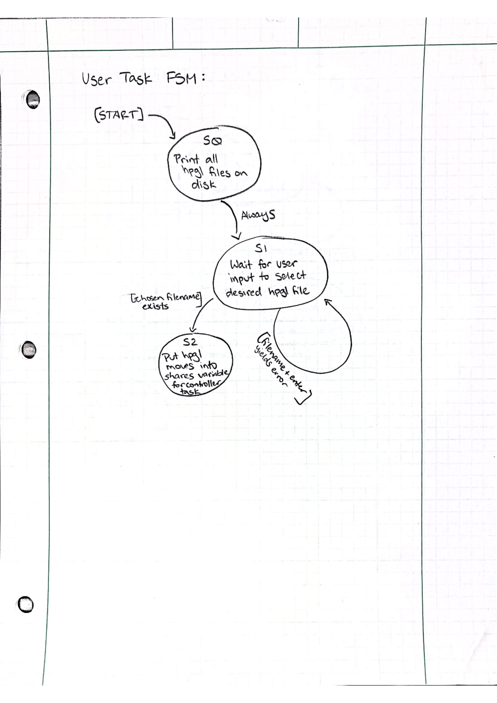
To make our lives easier we plan on using an xy plotting app to turn our drawings into usable coordinates. With these files copied to the Nucleo, we are able to import and read the x and y position coordinates using the open and readlines methods for our text files. Before we import the desired x,y position text file, we have to define which text file we would like to run on our engraver. This is done using a custom GUI that allows the user to select which text file they would like to run. Once the user has defined which text file they would like to run, the data points from the text file are imported and stored in a list. Once the data points are imported, we use our conversion factors to calculate the arm angles needed for our desired coordinates.
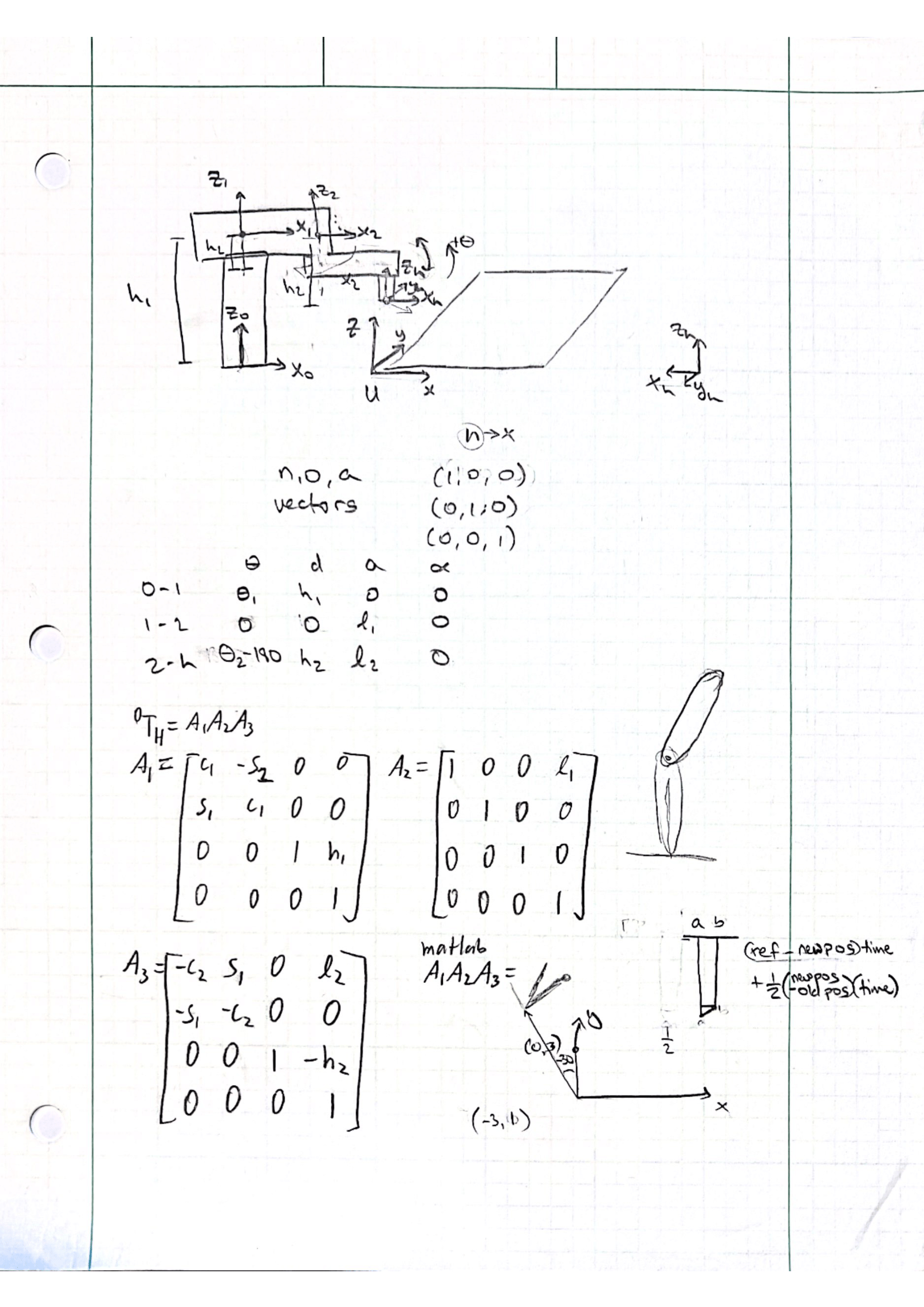
In order to calculate the angles for both rotational axes, we decided that using the Denavit-Hartenberg solution method would best suit our system the best. The Denavit-Hartenberg matrix representation enables the calculation of forward and inverse kinematics of translated coordinate frames using matrices. These matrices are defined by translating and rotating intermediate axes along the z and x axes to move from the base of our robot to the end effector (laser head). The derivation for our matrix values are included below for reference. Using the theta, d, a, and alpha terms for each translation we created a set of matrix multiplications which allowed us to calculate the angles needed to position the laser head at each given x,y coordinate location.
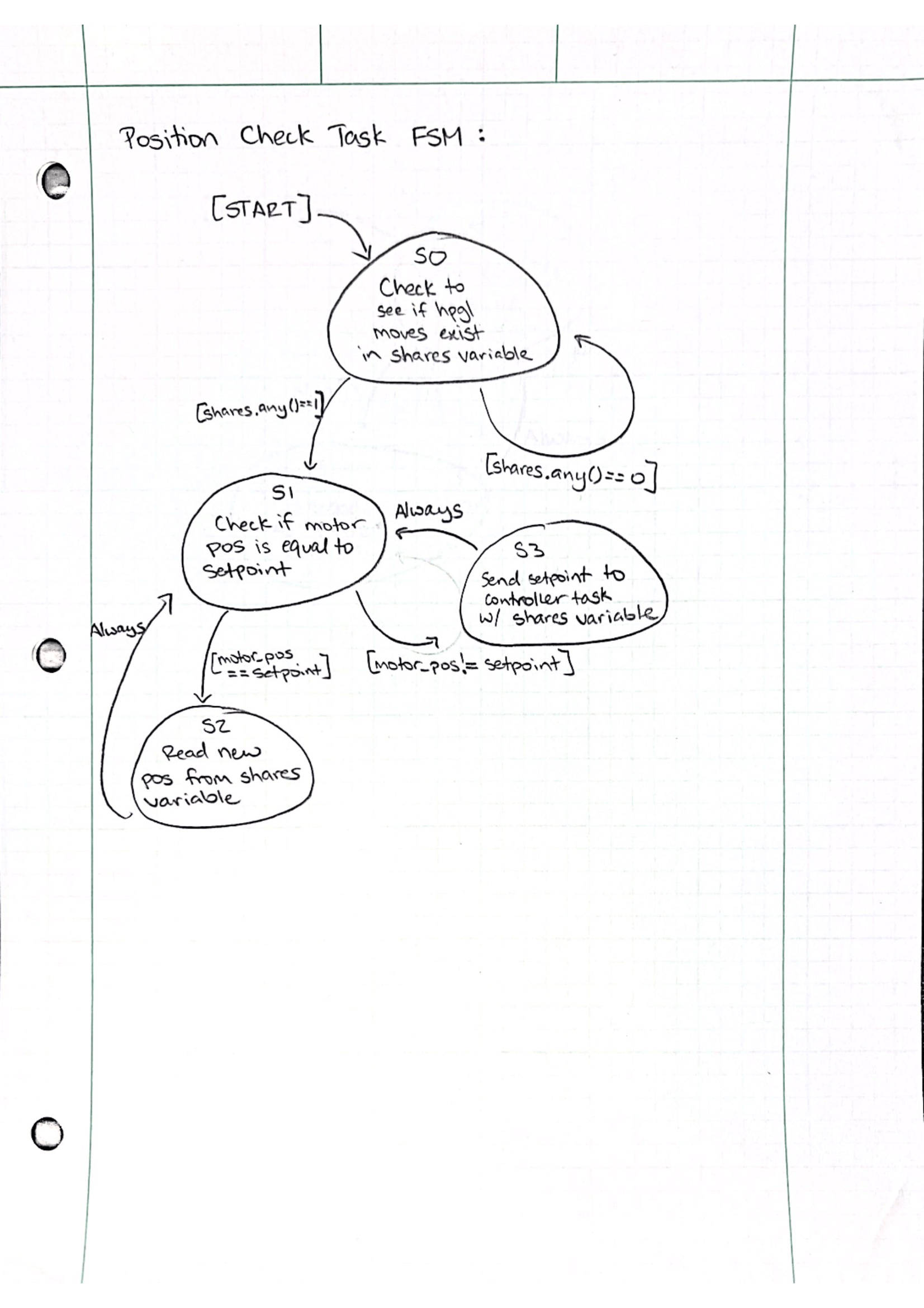
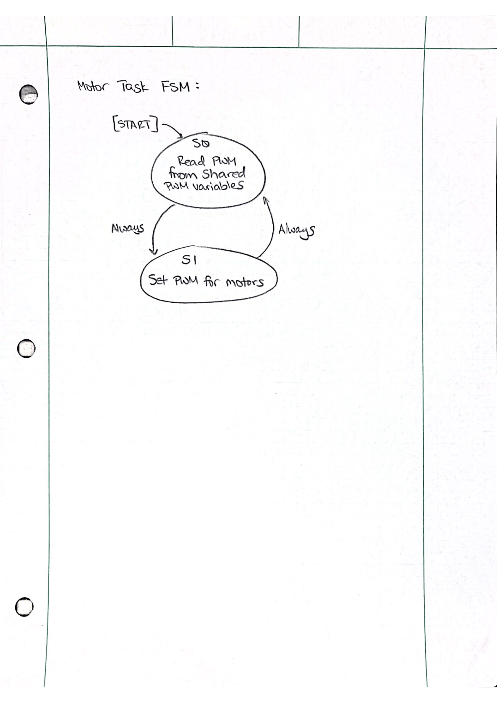
In order to control the robot, we needed to come up with a set of tasks that would be be performed over and over to move and control our two axes. The tasks we decided to use inluded a position check task, and a motor control task for each motor. The position check task was used to pull encoder position readings and check those values against the setpoint positions. If our error is within a given interval new setpoint values are pulled for each motor and the PID control scheme runs using new setpoints. The position check task is the most important, as we want to know when we hit each setpoint as accurately as possible. This task is then followed by the two moto control tasks, sending a new PWM to each motor every time they are run. Once the position check task runs out of encoder values the engraver is turned off and the motors are sent to their home positions.
In order to organize our project files, we wrote as many external files as possible with their own functions which we then called in our main script. The first method we call inside main is the user input function. This function is defined in the user_task.py file and allows the user to decide which text file will be imported for engraving. Once the text file has been read into main, we perform the necessary kinematic conversions to turn x and y positions into encoder tick values. To do this we call the inv_kinematics function in kinematics.py. This is followed up with the homing method written to home the two arms and zero the encoders at the given reset positions. This function is defined in the homing_script.py file and is called inside main.py. Once our arms are homed and encoders zeroed, we instantiate our position check and control loop tasks as tasks and begin our task scheduler with their respective periods and priorities. This control scheme runs until all x and y positions are hit and the robot is returned to its home location with the laser turned off.
Our task diagram for our SCARA robot is found below. We had a massive overhaul of our software structure since we started. Notably, we have three tasks with only two shares being used by the two motor tasks. Our third task, the positon checker, simply reads the current encoder value and determines if the motor has not moved. If this is the case, the setpoint has been reached and the next coordinate values are sent to each motor.
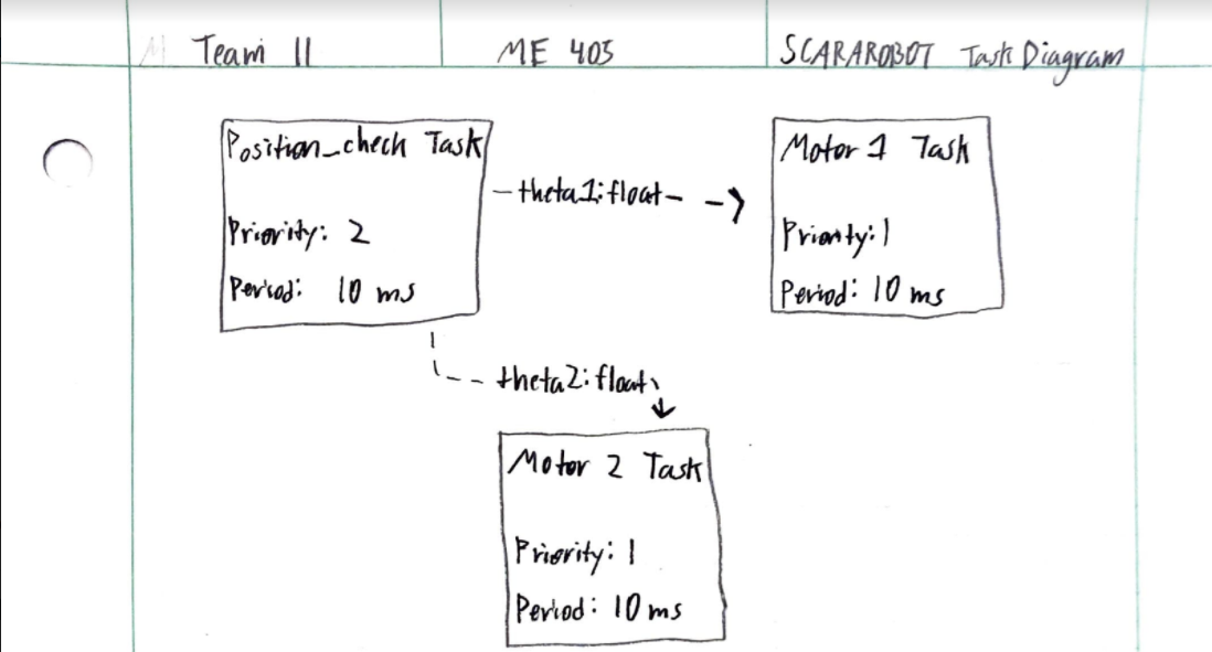
Our FSM diagrams have also simplified since we first embarked on our term project. While the user task is not a task within our scheduler, it is necessary for preprocessing as the user must select an image which then returns the x and y coordinates for that image. These coordinates are then fed into a queue which the position checker task utilizes. From here, the current setpoint is compared to the desired setpoint, at which the next values will be taken by the motor tasks. The motor tasks do not return anything nor change other tasks' states. The motor tasks simply retrieve the setpoint values which the controller then manipulates to deliver a necessary PWM.